
CAN Bus Communication in Automotive ECUs: Diagnosis and Troubleshooting
Modern vehicles contain numerous electronic control units that must communicate with each other to manage engine performance, transmission operation, braking systems and vehicle safety functions. The Controller Area Network (CAN bus) is one of the most widely used communication technologies in automotive electronics.
When CAN bus communication fails, multiple vehicle systems may stop working correctly. Diagnostic tools may lose communication with certain modules, warning lights may appear, and the vehicle may enter a protective operating mode.
Understanding CAN bus architecture and troubleshooting procedures is essential for automotive technicians working with ECU programming, electronic module repair and vehicle diagnostics.
1. What Is CAN Bus?
CAN bus is a communication protocol developed for electronic devices to exchange information through a shared network.
Instead of requiring a separate communication wire between every pair of electronic modules, CAN allows multiple control units to communicate through a common network.
In modern vehicles, CAN communication may connect:
- Engine Control Unit (ECU).
- Transmission Control Unit (TCU).
- Anti-lock Braking System (ABS).
- Airbag Control Module.
- Instrument Cluster.
- Body Control Module (BCM).
- Electric Power Steering Module.
- Gateway Control Module.
This architecture reduces wiring complexity and allows different vehicle systems to exchange information efficiently.
2. How Does Automotive CAN Bus Work?
A typical high-speed CAN network uses two communication wires known as CAN-H and CAN-L.
These wires carry differential electrical signals. The receiving modules interpret the voltage difference between the two lines to determine the transmitted information.
CAN-H
CAN-H is the high communication line. During dominant communication states, its voltage generally increases relative to the recessive state.
CAN-L
CAN-L is the low communication line. During dominant communication states, its voltage generally decreases relative to the recessive state.
Using differential signaling helps reduce the influence of electrical interference commonly found in automotive environments.
Exact voltage levels and signal characteristics depend on the CAN physical layer and network implementation.
3. Understanding CAN Bus Termination Resistance
Termination resistors help reduce signal reflections and maintain reliable communication on a CAN network.
A typical high-speed CAN network uses two 120-ohm termination resistors positioned at opposite ends of the main bus.
When measured across CAN-H and CAN-L on a properly configured, powered-down network, the expected resistance is often approximately 60 ohms because the two resistors are connected in parallel.
However, this value is not universal for every automotive network. Some vehicle architectures use different arrangements, switched termination or multiple network segments.
Before measuring resistance, follow the manufacturer's diagnostic procedure and ensure the network is in the required power state.
4. Different CAN Bus Networks in Modern Vehicles
Vehicles may contain several communication networks designed for different operating requirements.
High-Speed CAN
High-speed CAN is commonly used for powertrain and safety-related communication, including engine, transmission and ABS systems.
Low-Speed or Fault-Tolerant CAN
Some vehicle applications use lower-speed or fault-tolerant CAN networks for body electronics and other control functions.
CAN FD
CAN FD (Flexible Data-Rate) is an advanced CAN protocol that supports larger data payloads and higher data-phase bit rates than Classical CAN.
It is increasingly used in modern vehicle electronic architectures.
Multiple Network Architecture
Modern vehicles may use several CAN networks connected through a central gateway. This allows different electronic systems to exchange selected information while keeping network traffic organized.
5. Common Symptoms of CAN Bus Communication Problems
CAN bus faults can affect one module or multiple electronic systems depending on the location and severity of the problem.
Common symptoms include:
- Diagnostic equipment cannot communicate with an ECU.
- Multiple control modules report communication fault codes.
- Dashboard warning lights appear unexpectedly.
- Transmission communication is interrupted.
- Engine management functions operate incorrectly.
- Vehicle systems enter failsafe mode.
- Communication works intermittently.
When several modules report communication errors simultaneously, technicians should investigate the shared network before replacing individual ECUs.
6. Common Causes of CAN Bus Failures
Damaged CAN Wiring
Broken wires, damaged insulation and poor electrical connections can interrupt communication between control modules.
Short Circuit Between CAN-H and CAN-L
A short circuit between the two communication lines can prevent reliable network operation.
Short Circuit to Power or Ground
Damaged wiring may cause CAN-H or CAN-L to contact battery voltage or ground, creating network communication problems.
Incorrect Termination
Missing or defective termination resistors can cause signal reflections and unreliable communication.
Defective ECU Communication Transceiver
Many electronic control modules contain dedicated CAN transceiver circuits. Internal component failure may prevent the module from transmitting or receiving CAN messages correctly.
Gateway or Network Configuration Problems
A defective gateway, incorrect configuration or network management issue may prevent communication between different vehicle network segments.
7. How to Diagnose CAN Bus Communication Problems
A systematic diagnostic process helps technicians identify whether the problem originates from wiring, power supply, network termination or an individual control module.
Step 1: Scan All Available Modules
Use compatible diagnostic equipment to scan the vehicle and record communication-related fault codes.
Determine whether the problem affects one module or several modules on the same network.
Step 2: Check ECU Power and Ground
Verify the power supply and ground connections of the affected control modules.
A module with insufficient power may appear to have a CAN communication problem even when the network wiring is healthy.
Step 3: Inspect CAN Wiring
Use the correct vehicle wiring diagram to locate CAN-H and CAN-L.
Inspect connectors, harnesses and terminal conditions for corrosion, loose connections or physical damage.
Step 4: Measure Network Resistance
Where the manufacturer's procedure permits, measure resistance between CAN-H and CAN-L with the network powered down.
Compare the result with the specified network configuration rather than assuming that every vehicle must measure exactly 60 ohms.
Step 5: Analyze CAN Signals
An oscilloscope can help technicians inspect CAN communication waveforms and identify abnormal signal conditions.
It may reveal:
- Missing communication signals.
- Abnormal voltage levels.
- Signal distortion.
- Electrical interference.
- Communication interruptions.
Step 6: Isolate the Faulty Network Segment
If the network contains multiple modules or branches, follow the manufacturer's isolation procedure to determine which section is causing the communication problem.
Do not disconnect modules randomly, as some networks require specific termination and gateway configurations to operate correctly.
8. CAN Bus and ECU Programming
CAN communication is important when performing ECU programming through supported diagnostic and direct module connections.
Depending on the programming protocol, CAN may be used for:
- ECU identification.
- Diagnostic communication.
- Reading supported Flash memory.
- Writing supported software data.
- Communication with transmission modules.
- Electronic module configuration.
During Bench programming, technicians may connect directly to the ECU's designated CAN-H and CAN-L terminals.
However, not every ECU programming operation uses CAN. Some modules require other communication methods or specialized Boot procedures.
9. CAN Bus vs. LIN Bus
CAN and LIN are both automotive communication technologies, but they serve different purposes.
| Feature | CAN Bus | LIN Bus |
|---|---|---|
| Communication | Multi-master network | Single-master, multiple-slave |
| Wiring | Typically two communication wires | Typically one communication wire |
| Speed | Higher communication speeds | Lower communication speeds |
| Typical applications | Powertrain and vehicle networks | Body and convenience electronics |
| Cost | More complex | Lower-cost implementation |
CAN is generally used for systems requiring faster and more flexible communication, while LIN is commonly used for simpler electronic components such as certain window, mirror and seat control systems.
10. Choosing Professional ECU Diagnostic and Programming Equipment
Reliable diagnostic equipment is essential when investigating CAN communication problems and working with modern automotive control modules.
When selecting ECU programming equipment, technicians should consider:
- Vehicle and ECU manufacturer coverage.
- Support for different CAN communication protocols.
- OBD, Bench and Boot programming modes.
- Flash and EEPROM reading capabilities.
- Supported ECU identification functions.
- Connection diagrams and technical documentation.
- Software updates and technical support.
For professional workshops, compatibility with the exact ECU hardware and programming protocol is more important than general claims of vehicle coverage.
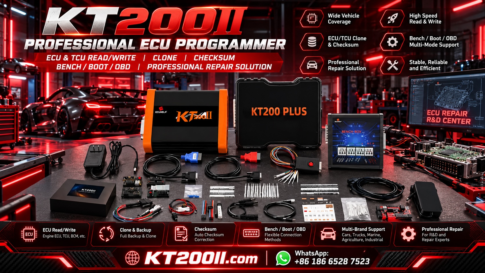
Visit KT-Prog to explore automotive ECU programming equipment and electronic control module solutions.
11. Best Practices for CAN Bus Troubleshooting
Following a consistent diagnostic workflow helps reduce unnecessary component replacement and improves repair accuracy.
- Identify the affected vehicle network and electronic modules.
- Read and record all communication-related fault codes.
- Check module power supplies and grounds.
- Consult the correct CAN wiring diagram.
- Inspect connectors and communication wiring.
- Measure network resistance where appropriate.
- Use an oscilloscope to evaluate signal quality when necessary.
- Isolate the faulty network segment using the manufacturer's procedure.
- Repair the underlying fault and repeat the communication test.
12. Conclusion
CAN bus communication is fundamental to modern automotive electronics. It allows different control modules to exchange information and coordinate important vehicle functions.
When CAN communication fails, the resulting symptoms can affect engine management, transmission operation and other vehicle systems.
Understanding CAN-H and CAN-L, network termination, wiring architecture and communication diagnostics helps technicians identify faults more accurately.
Combining systematic electrical testing with suitable diagnostic and ECU programming equipment allows automotive professionals to troubleshoot complex communication problems more efficiently.
For more information about automotive ECU programming technology and professional electronic control module solutions, visit KT-Prog.